A summary of my network configuration allowing isolated and private Internet access to specific networks behind a pfSense router and a Wireguard VPN, utilizing VLANs, firewall rules for isolating traffic and routing traffic out to my VPN provider. Complete with a VPN kill switch and Wireless Access Point configuration using a custom-flashed DD-WRT router running in Wireless AP mode.
A simplified diagram of my current network showcasing 3 main uses (there are more VLANs/subnets than need to be shown for the purposes of this post):
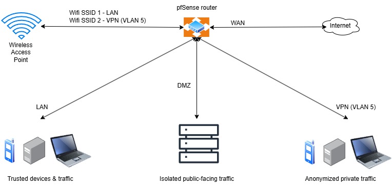
There are guides available on the web on how to tunnel all your traffic through a VPN in pfSense. I don’t want that – specifically what I want is to route particular subnetworks out through the service and leave my main LAN traffic alone.
The router I’m using is a pfSense instance – a virtual machine – running on one of the servers in a small cluster of virtualization hosts. My VPN provider, in this case, is NordVPN. They allow private Internet access through OpenVPN and Wireguard protocols. Their OpenVPN configuration files are available directly on their site, but their Wireguard connections are integrated into the client and authorized via your login credentials. Since Wireguard’s performance is notably better and tis configuration is simpler than OpenVPN, it’s the optimal choice in my use case.
What we are looking for is to extract their server authentication information, for which a private key (the authorized end user’s) and a public key (the server’s to which we are connecting), and a handful of other details to enable connectivity without having to use their software. If your VPN provider makes wireguard configuration files available, then this is not necessary.
There are other ways to retrieve the private and public key, but the easiest IMO is this, as follows, for Windows and Linux:
ON WINDOWs
Install Wireguard Windows client – https://www.wireguard.com/install/
Install NordVPN Windows client – https://my.nordaccount.com/downloads/nordvpn/
Connect to your desired NordVPN server. The integrated VPN client automatically selects the best server or you, or you can select on ein the closest city or state for you. NordLynx is the name of their renamed integrated version of Wireguard and is the default connection choice.
In Windows, open up a Powershell window with administrative rights. You can right click and selct “Run as Administrator” or right click the Start button and open Terminal or Powershell as Administrator.
Type the following to get your private key for NordVPN’s wireguard configuration:
wg show NordLynx private-key
Copy that key (you can highlight the key and right click to copy into the clipboard). Save that in a text file or a notepad window. We’ll need that later. This key is unique to your account credentials linked to your paid account. Don’t share it anywhere.
Next, we need the rest of the Wireguard configuration. Type:
wg show NordLynx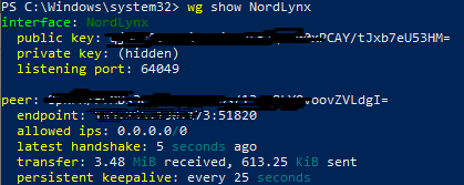
Copy and paste that information into a text file or a Notepad window.
Those are the pieces of information we need to get through Windows.
LINUX
For a Linux configuration, we need to install wireguard. In Ubuntu (this is what I’m using – steps will be slightly different on other distros), install the Wireguard client from the terminal through the official app repository
sudo apt install wireguardAfter wireguard, we need to install NordVPN. NordVPN does not have a GUI in Linux. I tested this in Ubuntu 24.04. (5/13/2025 – today NordVPN announced a Linux GUI – I may update this for the future, but for now the terminal client will continue to work so I’m leaving this as is)
Install NordVPN through the app store or terminal. Type
sudo apt install nordvpnNext, type
nordvpn loginwhich will prompt for additional commands to enter in the terminal in order to grant the snap of NordVPN client additional permissions to conect.. Copy and paste those commands one by one in the terminal window.
If you are not prompted for these addiitional commands for the login command, you will be for the following “nordvpn connect” command. In either case, you’ll need to run them at some point when you are prompted. Different distros do not use snap, so read the terminal output for any additional permissions you may need to grant there.
When done, enter “nordvpn login” again, and you will be presented a link you can right click on inside the terminal and open in the default web browser. Enter your login credentials, and once authenticated, you will be prompted to connect to NordVPN from the browser window back to the client.
Type
nordvpn connect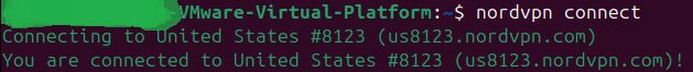
and you should connect to the closest/most optimal server NordVPN selects for you. If you’d like a specific server, you can enter
nordvpn -?to be presented with command line arguments to list which servers are available to cnnect to if you don’t want the automatically chosen server.
Next, we are going to run wireguard to extract the configuration information from the NordVPN connection.
sudo wg show nordlynx private-key
Followed by
sudo wg show nordlynx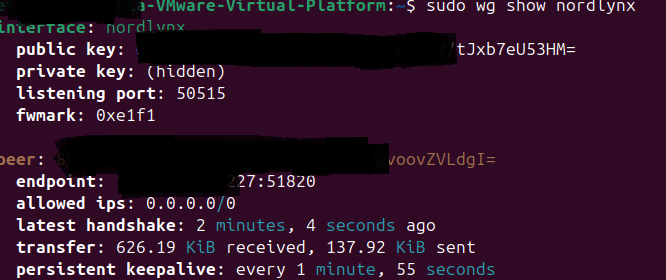
pfsense interface configuration (vlan or physical)
The next step is to configure pfSense with the wireguard tunnel.
First, check that a separate subnet has been created. This could be a VLAN or a physical connection (network card or phsysical port in a multiport NIC) tthat is assigned to a configuraable interface in pfSense.
As a VLAN:
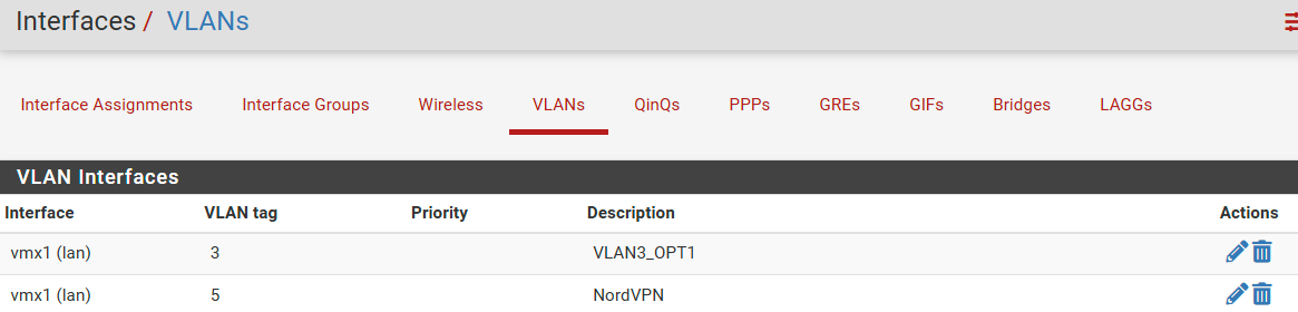
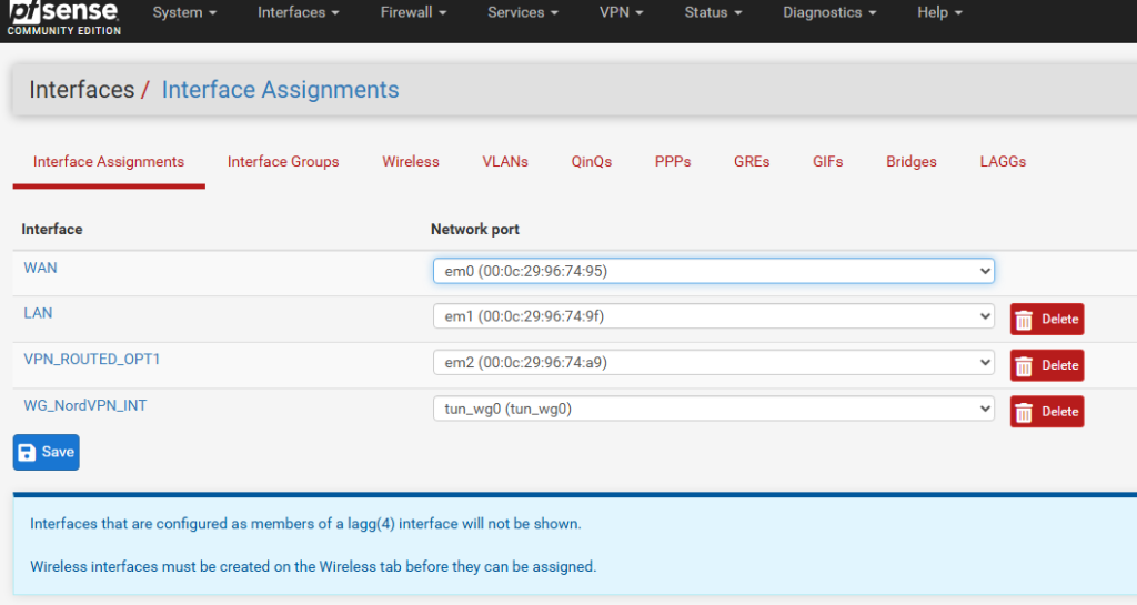
or physical (or virtualized emulating”physical” NIC in my case)
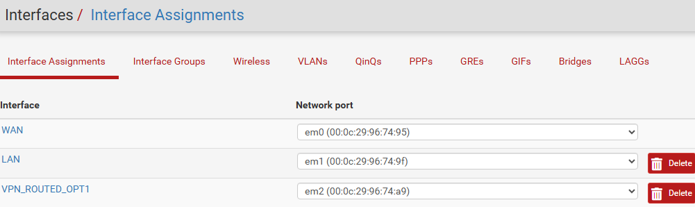
Whatever you choose, you need to assign an interface in pfSense to an available network port as in the above picture.
Click on Interfaces in the top pfSense menu bar and click the new interface to configure a new subnet(work) that you will configured to handle your new VPN-routed traffic. Here we need to assign it an IP address, the CIDR subnet range (/24 for my use, the equivalent of 255.255.255.0 subnet mask). Since my main LAN network in this demo is 192.168.1.0/24, this new network will be 192.168.2.0/24.
The interface address for this subnet is going to be 192.168.2.1. Click Save, Apply.
dhcp server
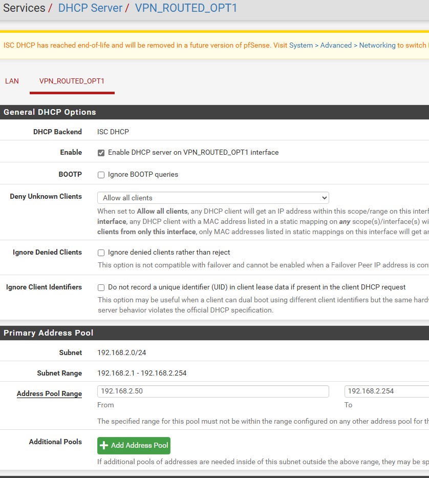
This is probably a good time to set up the DHCP server for this new routed interface. Click Services, DHCP server, select your newly assigned VPN-routed interface (hopefully you named it something beyond OPTx for easier identification), click Enable DHCP server… at the top,
Enter the desired IP range from the previouslyc onfigured /24 subnet. In my case, I chose 192.168.2.50*192.168.2.254. Change as desired. Click Save, Apply.
WIRGUARD TUNNEL & PEER
In pfSense, clck on System in the menu bar and select Package Manager. Under Available Packages, install Wireguard. If nothing populates in the Available Packages list, click on System, Update and then go back to the Package Manager for the list to be refreshed. This has happened to me in the past and this little update check fixed the list not loading.
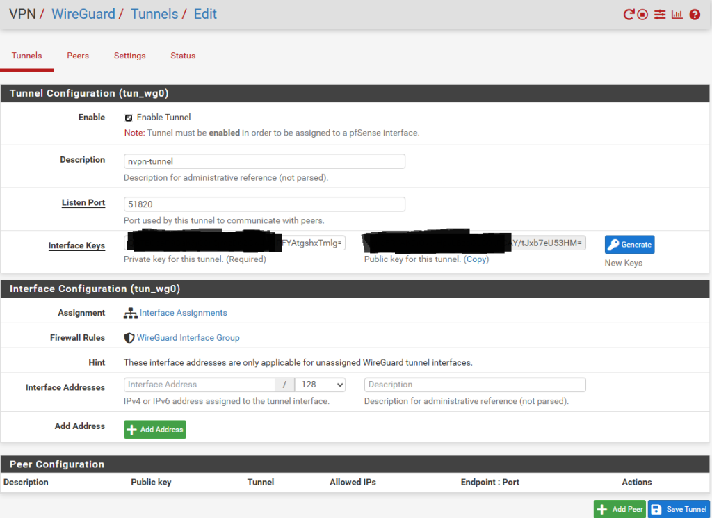
Next, click on VPN in the menu bar, Wireguard and in the Tunnels section, click Add Tunnel.
This is what my entries look like ifor the tunnel. You’ll need to copy into the “Private Key” field the private key you saved from the earlier steps above. When you click outside in a black area of the form, the public key will be automatically computed for you from the private key Click Save Tunnel to continue.
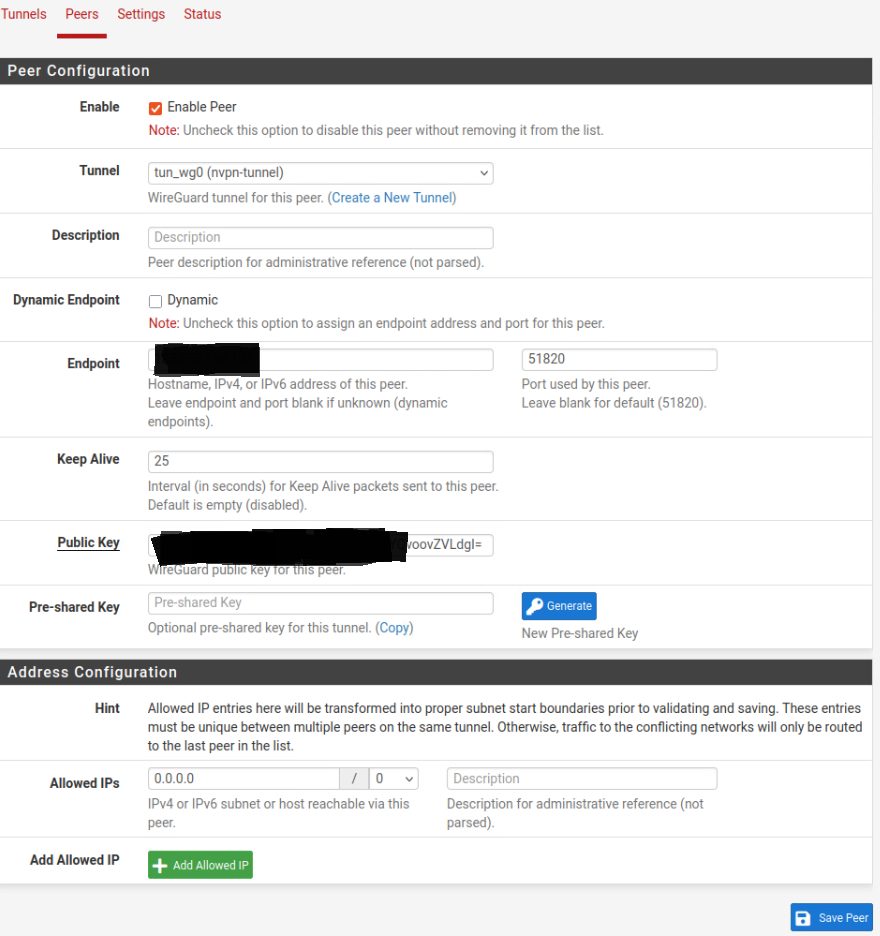
Next click on the Peers tab and click Add Peer. Under Tunnel, select “tun_wg0” that corresponds with the just-created tunnel, uncheck Dynamic to make the fields accessible and enter the IP address from the configuration copied earlier in the Endpoint field.
Enter the Public Keyfrom the “peer” section of the saved configuration into the proper field and under Allowed IPs enter 0.0.0.0 and select 0 for the CIDR subnet mask. Make sure to check “Enable Peer” and click Save.
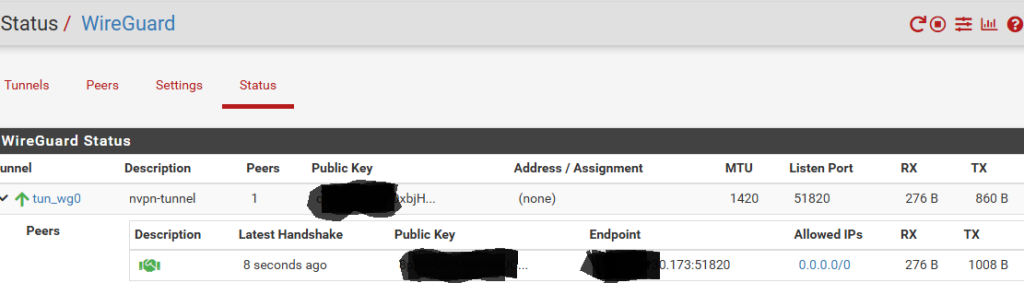
The service should start automatically and connect, but if it doesn’t, you can click the little > “play button” at the top right corner of this page to start the Wireguard service.. Verify that the peer has connected through the tunnel interface you created:
WIREGUARD INTERFACE & GATEWAY
At this next step, we will assign a pfSense interface to our newly connected and peered tunnel interface. Click “Interfaces” in the pfSense menu bar, then Assignments. Under “Available network ports”, choose “tun_wg0” and click the +Add button. Click Save.
Select the newly created interface from the Interfaces menu (mine was OPT2 by default), and click the “Enable interface” checkbox. In IPV4 Configuration Type drop down menu, select Static IPV4 and in the IPV4 address field, enter the IP Address 10.5.0.2/32 I renamed the description field _WG_NordVPN_INT for easy identification.
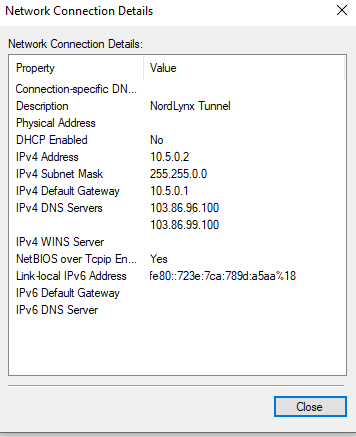
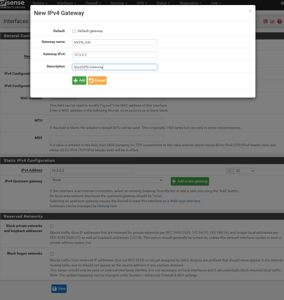
In the IPV4 upstream gateway, click “+ Add a new gateway”, optionally rename to something more descriptive, and enter 10.5.0.2 in the Gateway IPV4 field. (The same as the IP entered in the Interface IPV4 address prior. Click +Add. Then Save and Apply.. NordVPN uses 10.5.0.2 for the tunnel interface address, which can be seen in this Windows configuration screenshot.
outbound nat
Next we wll configure the Outbound NAT rules for this subnet to route out via the new VPN gateway we just created.
Click on Firewall, NAT, Outbound, change the default Mode from “Automatic outbound NAT” to “Hybrid Outbound NAT” and click Save.
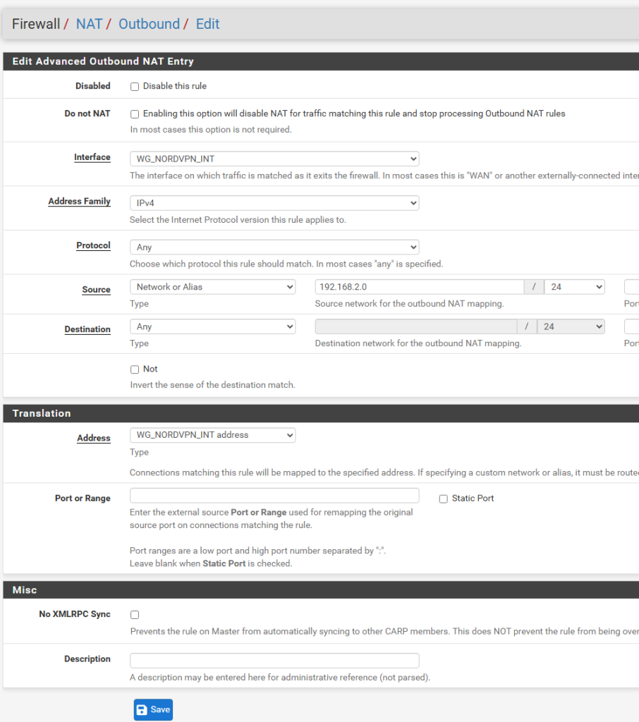
Next, click on the first Add button, in the Interface list, select your Wireguard interface you created above in pfSense (mine is named “WG_NORDVPN_INT”), and fill out the rest of the fields as seen below.
Note that the address family is IPV4 only in my case, as NordVPN does not support IPV6. Under Source select “Network or Alias” and complete the field with the network address and CIDR mask you created in the first interface we configured above (OPT1 in my case – renamed to VPN_ROUTED_OPT1)
In the Translation section, under Address, select the Wireguard assigned interface address from the list (mine is called WG_NORDVPN_INT address”. Click Save.
ip alias & packet tagging
To prepare for the kill switch in another step, we will create an Alias for the range of IPs we want routed out ONLY THROUGH THE VPN with no way to leak out into our WAN. This step allows us to specify only some IP addresses or the enire subnet range. I’m including it here as I think the tagging of the packets through the pfSense data path is a neat feature that can be useful in different scenarios. In our case, this is important in case the VPN tunnel loses its connection, the rule we will later create blocks these Aliased IPs through what are known as floating rules (i.e. not statically linked to an interface).
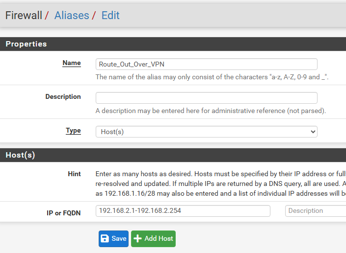
Click on Firewall, Aliases, + Add, and enter a descriptive name (I chose “Route_Out_Over_VPN”), and in the “IP or FQDN” field enter the desired subnet range. In my case, that’s 192.168.2.1-192.168.2.254. Click Save.
firewall routing rule
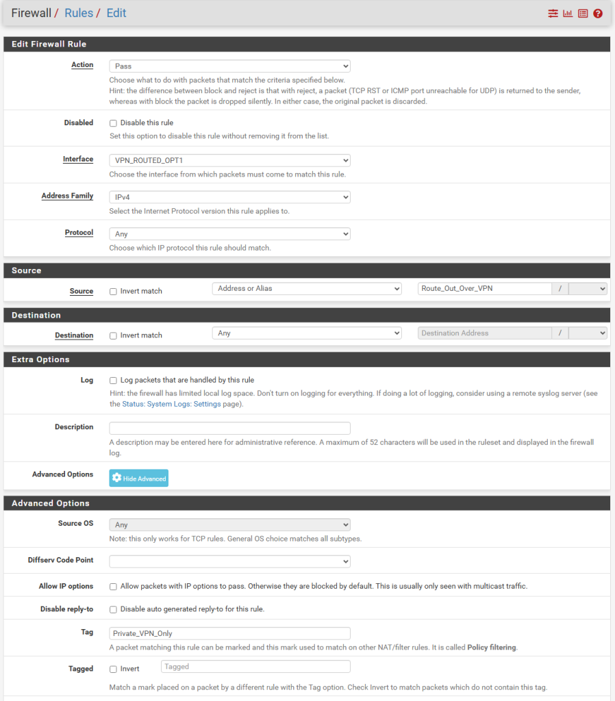
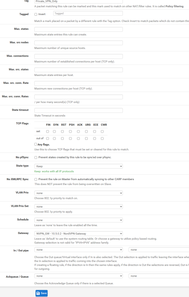
Next we will configure routing for our VPN-only subnet in the firewall rules. Click Firewall, Rules, select the interface we created for the VPN-routed IPs, (VPN_ROUTED_OPT1 in my case here). Click the Add button.
In the following fields, select IPV4 for address family, Any for Protocol, in Source, select “Address or Alias” and start typing “Route_Out_Over_VPN” and the field will auto-populate. Select the previously created Alias, and now the cool trick of tagging packets will be set up.
Click the “Display Advanced” button and in the Tag field, type a name that you will use in a later rule. I chose “Private_VPN_only”. This marks the packets we are routing out over the VPN so we can identify them in a different rule later on that we’ll use in the kill switch floating firewall rule. It’s a good idea to copy the Tag’s name into the clipboard because we need to enter it exactly as is in the floating rule step.
Further down, in the Gateway drop down list, select the gateawy you created earlier, which I’ve called NVPN_GW. Click Save.
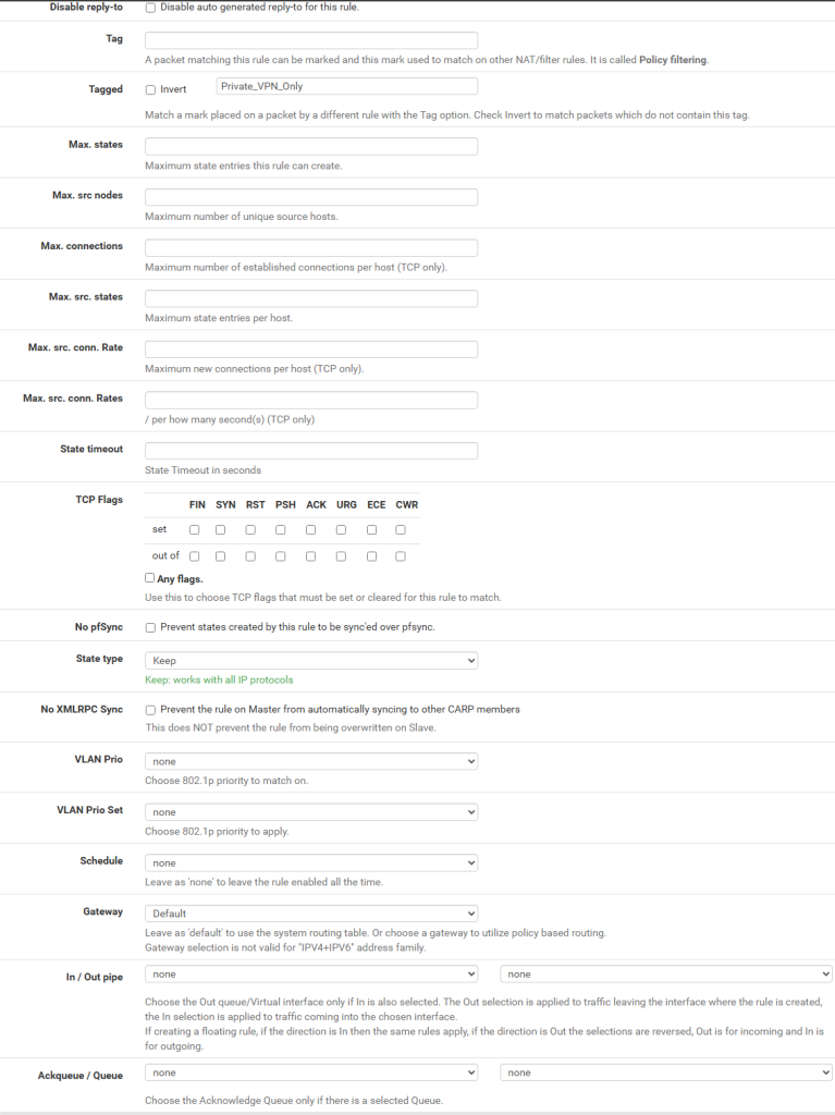
KILL SWITCH
For this next part, we’ll use pfSense’s firewall floating rules. These rules are not attached to a specific interface, and are helpful in stopping pfSense routing packets through the default WAN Gateway in a situation when the VPN Gateway is no longer reachable. This is where the packet tagging from earlier in the configuration come in handly.
Click Firewall, Rules and in the Floating section, click Add. Under Action, select Block and under Interface, select WAN. and under Protocol, select Any.
Click Display Advanced button and under Tagged (not Tag – we’re looking for already tagged packets at this step), paste the tag we used earlier. My example is “Private_VPN_Only”. Click Save.
A test with conecting a VM or a physical PC to the 2nd port (OPT1) of pfSense VM (or physical router) will show that you are receiving an IP in the 192.168.2.x range and a cursory check on https://www.whatismyipaddress.com shows a different IP and Internet provider than that on the LAN.
Wireless setup with dd-wrt wireless access point
The Wireless Access Point is a flashed Linksys I came across on a deal found online. It has been flashed with DD-WRT firmware. This is not a guide on how to flash that, simply a basic configuration guide on how I created multiple SSIDs for both my main LAN subnet and my VPN subnet so i can switch freely between them.
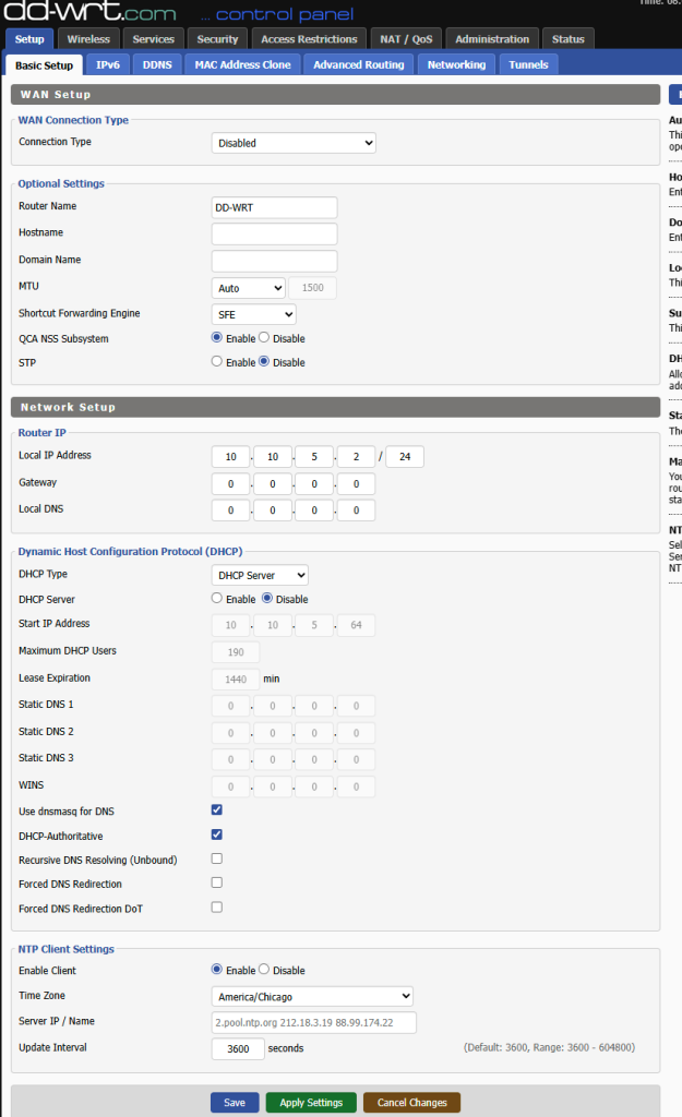
This little router does not need to do any routing, but simply will be functioning in Access Point (WAP) mode. That means we need to disable its DHCP server.
In the first, default settings page, “Basic Setup”, feel free to leave everything as default apart from disabling DHCP server and assigning a Router IP in the same subnet as my main LAN.
Since this is my main WAP device, the IP settings will be different than what we set up above. For illustration purposes, I’ll share here the actual IP configuration page as it is currently configured. These should be changed to reflect your own configuration.
This particular device’s firmware does not have a Switch ports configuration menu. It can be accessed via http://<router ip>/vlan.asp but I don’t know if it works at all and for my use case it’s irrelevant.
In my situation, I want to tag specific physical ports (wan/lan 1/lan 2/lan3 – aka eth0, eth1, eth2, eth3 on this device) with VLAN 5 traffic., where in my network, VLAN 5 is where I’ve placed VPN-only traffic.
In other words, they become virtual interfaces within the Linksys router + AP device, which is then tagged with VLAN 5 traffic. I will create a bridge with specific interfaces that I want to be be bridged together. The default untagged br0 bridge on the default VLAN 1 and a new br1 bridge that will bridge traffic from the trunked VLAN 5 virtual interfaces and my separate, VPN only Virtual AP (Virtual Access Points with separate SSIDs).
This will make sense in a second with the screenshots below. First, let’s set up the various wireless radio interfaces. This router + AP combo has 3 separate wireless radio interfaces. i’ve disabled wlan0 since it’s limited in radio functionality and meant for mesh network functionality with its original Linksys firmware. It’s usable but I don’t need it.
For the other 2 wlan interfaces that are enabled, I’ve added an additional Virtual AP, which essentially provides a separate virtual Wifi interface to connect to. You can tell them apart from the added “-nv” to the default, LAN accessible SSID to signify NordVPN. One runs on the 2.4 Ghz radio frequency range, and the other in the faster, but less penetrable 5 Ghz frequency. The only major modification here is that I’ve let them use full channel width. This is optional.
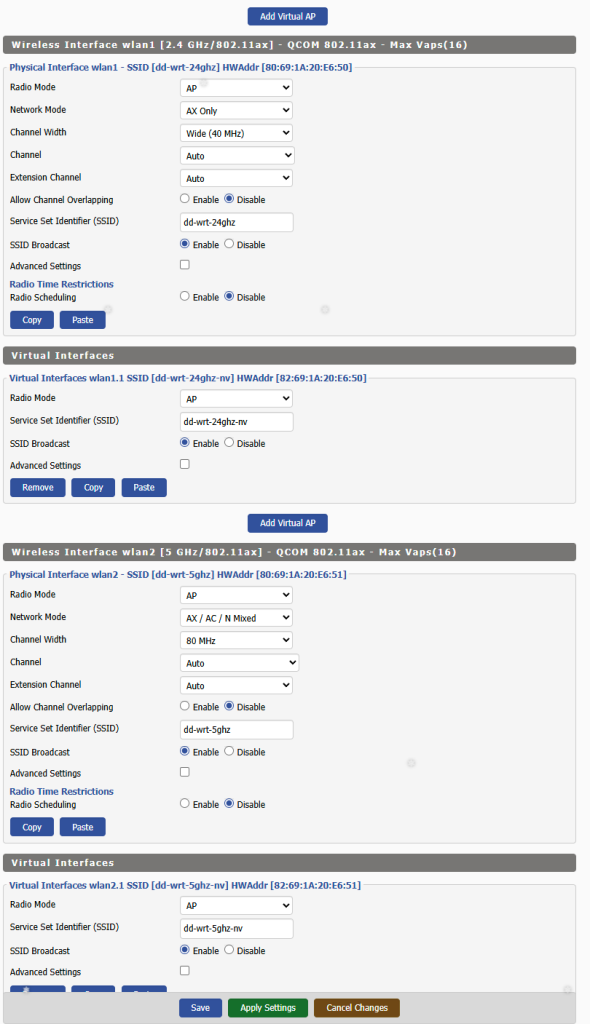
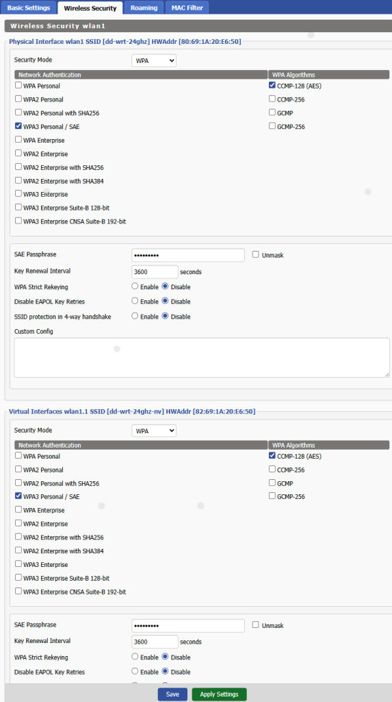
The next screenshot shows the Wireless Securty settings. These are pretty generic, WPA3 with a supplied password. You will notice the virtual sub interface is named wlan1.1 and wlan2.1 respectively. Not fully visible in this partial screenshot.
Once these are set up, we’ll go in te main Setup tab of DD-WRT’s web interface and select the Networking tab. Here you will notice taht I’ve tagged all phsyical interfaces with VLAN 5, so that tagged traffic passes through. They essentially become trunks carrying VLAN 5 only, in this case. Recall this is strictly a router running in dumb AP mode, simply serving as a wireless interface to the LAN and my isolated VLAN 5 with VPN access.
I’ve create a bridge called br1 in addition to the default br0 bridge and bridged all .5 (VLAN 5 tagged) subinterfaces together. In addition, i’ve added the two wireless virtual interfaces to the bridge as well. This does the magic that bridges every device that connects to my -“nv” labeled Wifi SSIDs to my VLAN 5 isubnetwork in pfSense and gets served an IP address from there and is routed out over the VPN connection we created early on.
Every connection to the non “-nv” labeled SSID stays on the “trusted” LAN network with open connectivity to the Internet in comparison.
Let’s review.
- We’ve set up in pfSense a separate VLAN-routed subnet.
- Connected via Wireguard client to a Wireguard server (in this case the NordVPN VPN provider – this could be any other Wireguard server, including your own privately hosted one or via a third party provider.
- Set up a kill switch in case the Wireguard tunnel goes down so that our traffic doesn’t go out the WAN connection unprotected.
- Set up a DD-WRT Wireless Access Point so we can easily access the VPN subnetwork directly via Wifi
There are other things you can do, to further enhance your privacy like setting up pfSense with NordVPN’s DNS servers so your DNS queries do not leak to your ISP. I don’t find it neccessary personally, but I do use DNSSEC with Cloudflare’s 1.1.1.1 and Quad9’s 9.9.9.9 DNS servers in the pfSense General Settings page for relative privacy.